Class-D Amplification Explained
If you're under the impression that Class-D amplifiers are just 'two letters worse' than Class-A models, think again: Class-D technology is making an increasing impact on the live sound world by offering more power with less weight than ever before. We find out how and why...
Every sound engineer has an opinion about microphones. And loudspeakers, they certainly all sound different. Mixing consoles? The differences there are down to facilities and operational convenience. But power amplifiers? Apart from 'bigger is better', who could get excited about an amp? The power amplifier, possibly several of them for a live show, sits in a rack and gets on with its job. The technology is mature and there isn't all that much difference between power amplifiers, so you simply choose a reliable manufacturer and the required power rating. Rack up, and you're done.
We should be thankful that power amplifiers are so uninteresting, because if they're uninteresting it means that they work well. Indeed, the power amplifier is one of the best-performing pieces of kit in the entire sound system, in terms of frequency response, distortion and noise. Modern power amplifiers are also generally a pretty reliable bunch. Amplifiers of old used to die on a regular basis as their transistors spontaneously combusted. But now, thanks to efficient cooling and protection circuitry, power-amp failure is a comparatively rare event (if you don't find that so, look to your cooling - free air-flow is a must).
Still, manufacturers don't like to rest. They need to improve their products continuously, hopefully to gain an advantage over their competitors and encourage us to buy more of what they make. As it happens, there is still room for improvement in the field of power amplifiers. More watts for the buck is one way they can be improved. Simply more watts in a single amplifier is another. A third potential area for development? Make them lighter! If you've ever spent time rigging amps and amp racks, you'll know all about that.
Here's a good question; just why are power amplifiers so heavy? Electricity doesn't weigh anything, so how come amps have so much mass? There are two answers to that. One is the transformer that converts the mains voltage into a lower voltage suitable for the amp's circuitry. If an amp is rated at 500 Watts, for instance, the transformer has to be able to supply all that power, and more. So it needs substantial copper windings and a bulky core; it's bound to be heavy. The other potentially massive item is the heat sink. Not all of the electricity supplied to the amplifier circuitry is converted into useful power sent to the loudspeakers. Some is wasted as heat, and this heat has to be dissipated, otherwise the amp will cook. So the output transistors are bolted to a large, finned heat sink with a broad surface area that can lose heat easily, particularly when used in conjunction with a fan. It is true that heat sinks can be made from a lightweight metal such as aluminium, and clever design can make the heatsink part of the amp's structure. Even so, everything adds up and the typical power amp is a pretty weighty beast.
To reduce the weight of an amplifier, there is a simple solution: don't waste so much power. If no power were wasted, the transformer could be much smaller and a heat sink would not be required. Clearly, there never will be a 'no-waste' amplifier, but the more efficient an amplifier is, the lighter and smaller it can be. So in live sound, where power amps are used in quantity, efficiency in an amplifier is a very desirable quality. In other areas where power amplifiers are used, such as home hi-fi and studio monitoring, efficiency isn't such an issue.
This brings us to the topic of this article: Class D amplifiers. The whole reason for existence of Class D is efficiency. Plainly, there must also be Class A, Class B and Class C, and one would expect these to be earlier developments, as they come before D in the alphabet. We're going to explain how Class D works, and why it is suitable for live sound. But first, we're going to have to explain how all those other classes work.
In The Beginning...
If you don't know anything about electronics, don't worry. Well, don't worry much - We're not going any deeper than an existing understanding of how a battery and bulb work (of course, a little knowledge of audio signals won't go amiss).
In the beginning was the single-ended Class-A amplifier, as shown in Figure 1. We've simplified the schematic to show only the output device, which is where the differences between the classes are defined. In a simple amplifier like this, the audio input signal - a small alternating current (AC) - flowing into the base of the transistor ('b') controls a larger direct current (DC) flowing from the output of the amplifier's power supply through the collector ('c') and emitter ('e') to earth. The parts of the circuit we have left out, 'bias' the transistor so that when there is no input signal, the output voltage (ie. the voltage at the collector) is half the total supply voltage. This allows the output voltage to vary both up and down to an equal extent, to recreate the AC waveform of the input. If the voltage with no input-signal present was to be anything other than halfway between zero and the full power-supply voltage, then inevitably one half of the waveform would run out of volts before the other, limiting the amount of amplification available before the waveform would be clipped.
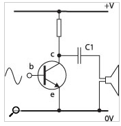
Figure 1: A simple single-ended Class-A amplifier
Let's look at what happens when the input signal voltage to the transistor is low. The transistor will allow only a tiny current to flow between the collector and emitter, therefore the voltage at the collector will be almost the same as the full supply-rail voltage. So the load (the loudspeaker) is driven with a high voltage and a strong current - Ohm's Law, V=IR (Volts = Current x Resistance), dictates that current flow is always proportional to the voltage applied and the resistance within the circuit. Conversely, when the input voltage to the transistor is high, the collector-emitter part of the transistor will conduct. The voltage on the collector will become low, so the load (the speaker) is driven with a low voltage and only a small current (Ohm's Law again; the resistance of the speaker remains the same, but the applied voltage is now low, so the current flow is low). As the input signal waveform feeding into the transistor cycles up and down, so does the output voltage. The output voltage is a bigger version of the input voltage - which, of course, is the whole point of amplification.
This raises some questions. Firstly, why is the load (the loudspeaker) not simply connected between the supply rail and the collector? The answer is that, if it were, a current would always flow through the loudspeaker, even when no input signal was present. That would a) be wasteful, and b) displace the cone of the loudspeaker from its rest position, even when there was no signal. The second question is why is there a capacitor (C1) between the collector and the loudspeaker? The answer is to prevent the actual (DC) current of the power supply reaching the speaker, as it's only the changes in voltage that we are interested in, and a constant applied voltage would, as above, offset the cone from its rest position (for the sake of simplicity, I'll leave out the explanation for the resistor).
This simple amplifier is known as 'single-ended, Class A'. It has only one output device, and when there is no signal the current through the output transistor is at least as great or greater than the maximum current that ever flows through the loudspeaker. So the Class-A amplifier is working flat out even when there is no signal! A Class-A amplifier can only ever be 25 percent efficient, according to the mathematics. So even working at its best, three quarters of the input power is wasted.
You Push, I'll Pull
Figure 2 shows an alternative strategy, in the form of a push-pull amplifier output stage. One transistor 'pulls' the voltage up on the positive half-cycle of the waveform. The other transistor 'pushes' the voltage down on the negative half-cycle. Well, that's the kindergarten explanation. Let's look in a little more detail...
In this version, we have shown both a positive supply rail and a negative supply rail, as well as an earth exactly in between in voltage; zero volts in fact. A single-ended (positive- or negative-only) power supply can be used, but a dual-rail supply is better, as no DC-blocking output capacitor is necessary. This is because, when there's no signal, both terminals of the loudspeaker are at zero volts, so no current flows and there is no DC to be blocked. You will notice that the transistors are slightly different to each other. The upper transistor (Q1) is what we call 'npn', meaning that it will conduct between collector and emitter for a positive voltage at the base. The lower transistor (Q2) is 'pnp', meaning that it will conduct between collector and emitter for a negative voltage at the base. If you're into electronics already, you will have noticed that there is another difference between this and Figure 1. In Figure 2, the loudspeaker is connected to the emitters of the transistor, rather than the collector of the transistor in Figure 1. This means that all the voltage amplification has to precede this stage. This part of the circuit is responsible for delivering a high current to the loudspeaker. But don't worry too much about that; it doesn't affect my explanation of the amplifier classes.
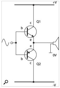
Figure 2: Push-pull Class-B amplifier
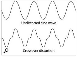
Figure 3: Crossover distortion
In this configuration, a high input voltage will cause Q1 to conduct, bringing the output voltage close to the positive supply-rail voltage. A zero input-voltage will cause neither transistor to conduct. The output is at zero volts. With neither transistor in conduction, clearly no current is available for the loudspeaker. But since there is no voltage across the terminals of the loudspeaker, it doesn't need any (a handy coincidence). When the input voltage is low, Q2 conducts, allowing the voltage at the output to descend almost to that of the negative supply-rail. From this, you can see that Q1 handles the positive half-cycles of the waveform and Q2 handles the negative half-cycles. This is Class B.
The beauty of this arrangement is that it is much more efficient. When the input signal is zero, there is no current flowing either through the loudspeaker or through the transistors. The maximum theoretical efficiency for a sine-wave input is 78.5 percent - a vast improvement over Class A.
But there is a fly in the ointment. A transistor will conduct hardly at all if the voltage on the base is less than 0.6 volts (minus 0.6 volts for a pnp transistor). So input voltages between -0.6 and +0.6 volts will not stir either transistor into conduction. Figure 3 shows the consequence. That flat spot in the middle of the waveform is called 'crossover distortion' and is an intrinsic feature of Class B. Fortunately, there is an answer, and that is to 'bias' the input to the two transistors, as in Figure 4. Those two new components between the bases of the transistors are diodes. Their effect is to separate the standing voltages on the bases by 1.2 volts, thus overcoming the intrinsic 'inertia' of the transistors. The input signal now only has to twitch and the transistors will respond. This is a simplification of a real-world circuit, but only slightly so. In a real circuit, the voltages on the bases of the transistors would have to be slightly further apart, and adjustable to set the 'quiescent current' (the constant current when no input signal is present).
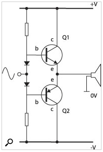
Figure 4: Class-AB amplifier (simplified)
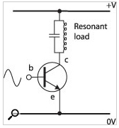
Figure 5: The comparator of the Class D amplifier, generating a pulse-width modulated signal
The benefit here is that crossover distortion is almost eliminated, at the expense of a slight standing current when the signal is at zero level. It is interesting to note that the biasing could be arranged so that the transistors carried a very high current for a zero input signal. When the input moved, this current would be diverted through the load. Guess what? This is Class A again. It's a push-pull Class-A output stage, no more efficient than a single-ended Class A, but more practical to implement, and entirely lacking in crossover distortion, which is why it is admired by high-end hi-fi enthusiasts. The compromise situation of biasing the output transistors so that they are just in conduction is called Class AB. Class AB is far and away the most common type of amplifier. It's reasonably efficient, and its sound quality is excellent, surpassed only by Class-A amplifiers that run as warm as an Aga and cost the earth - both to buy and to run.
To round off this section, Figure 5 shows a simple Class-C amplifier. It drives a resonant load and is thus very efficient at the resonant frequency of the load - over 90 percent. However, since it only works over a narrow range of frequencies, it is entirely unsuitable for audio. Class-C amplification is actually used in radio transmission.
He Ain't Heavy, He's My Class-D Amplifier
Now that we know how classes A, B, AB and C work, we can look at Class D. Clearly, classes A to C are all in the same family, but Class D is completely different. In Classes A, B and AB, the problem is lack of efficiency. Some power is wasted, and we would prefer that it could be sensibly employed in driving the loudspeakers to ever-higher sound pressure levels - or, at least, not converted to heat. Where power is wasted is where a transistor is in partial conduction. When a transistor is fully conducting, it's like a piece of wire, and a piece of wire loses hardly any power. When a transistor is fully off, it doesn't conduct at all, and if it doesn't conduct at all, there's no power to waste. It's the in-between stages that cause the problem, where the transistor wastes power and gets hot. So what if we could find a way for transistors to be used only in their fully-on or fully-off states. If that were possible, no power would be lost. But is it possible...?
It is, and the solution is what we call Class D. Figure 6 shows a simplified Class-D amplifier. First, let's look at the similarities between this and what we've already discussed. You can see two transistors, in push-pull configuration, as before. The transistors look slightly different because they are MOSFETs (Metal Oxide Semiconductor Field Effect Transistors) rather than 'ordinary' transistors. The output transistors have to be fast, so that they can switch very quickly between fully on and fully off. It also helps for the on and off states to be 'really' on and off. The closer the transistors can get to full conduction or full non-conduction, the greater the efficiency of the amplifier will be. Clearly, though, as well as the similarities there are some differences.
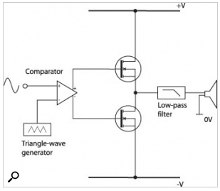
Figure 6: Class-D amplifier
Let's start at the output. What's not going to happen is that the transistors create a high-voltage version of the input signal. What is going to happen is that they switch alternately to lift the output all the way up to the positive supply rail, then all the way down to the negative supply rail, as quickly as possible, with no in-between voltages. This is clearly going to be a pulse waveform. Now here's the clever bit: if the width of the pulses can be made proportional to the input signal's instantaneous level, the power delivered to the loudspeaker, averaged over time, will be the same as if the input signal had been amplified in the conventional way. Think about that for a moment, because it's key to how a Class-D amplifier works.
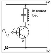
Figure 7: The comparator of the Class D amplifier, generating a pulse-width modulated signal
Going further, if the output is filtered to remove the high frequencies and sharp corners of the pulse waveform, the original input signal will be reconstructed, exactly the same shape as it was, but bigger. The net result is an amplified signal that you couldn't distinguish from that produced by a conventional Class-AB power amplifier.
But how is the pulse waveform produced? OK, it isn't simple, but it isn't rocket science either. First we need a circuit building-block known as a comparator. A comparator has two inputs: let's call them Input A and Input B. When Input A is higher in voltage than Input B, the output of the comparator will go to its maximum positive voltage. When Input A is lower in voltage than Input B, the output of the comparator will go to its maximum negative voltage. Figure 7 shows how the comparator operates in a Class-D amplifier. One input (input A in our example) is supplied with the signal to be amplified. The other input (input B) is supplied with a precisely generated triangle wave. When the signal is instantaneously higher in level than the triangle wave, the output goes positive. When the signal is instantaneously lower in level than the triangle wave, the output goes negative. The result is a chain of pulses where the pulse width is proportional to the instantaneous signal level. Magically simple! We call it 'pulse width modulation', or PWM. And that's all there is to it. You now understand how a Class-D amplifier works, and if anyone tries to pull the wool over your eyes and convince you that the 'D' stands for 'digital', you can tell them how wrong they are, with confidence. Class D is not digital.
That's Not All, Folks
Clearly, there is more to know. For instance, it's important to know that the switching frequency must be very high to achieve the necessary resolution. A switching frequency of around 300kHz, which is around 15 times the highest audio frequency of general interest, is typical. The dynamic range and signal-to-noise ratio of the Class-D amplifier are controlled by the switching frequency - the higher the better. Clearly, the greater the rate of pulse generation, the more closely the pulse width will be in proportion to the instantaneous signal level. However, the drawback of increasing the switching frequency is that the amplifier will be less efficient. Optimum efficiency would be achieved if the transistors could switch instantaneously, so that they were in either their fully on or fully off states, where almost no power is consumed. But in the real world it takes a little time for the voltage to swing, and during that time some power is dissipated. So the more often the swings take place, the more opportunity for waste. Even so, the efficiency of a practical Class-D amplifier can be better than 90 percent, which is significantly better than a Class-AB design (78.5 percent at best and typically closer to 50 percent).
Coming full circle, because a Class-D amplifier is more efficient than the conventional Class-AB one, it can be lighter. And that, in a nutshell, is the reason for Class D's existence. Lighter also leads to smaller, and to achieve the high switching speeds necessary, the circuitry has to be physically small. Look inside a Class-D amplifier and you'll find a transformer. Look hard enough and somewhere in there you'll find the circuit too!